
MRR Speedometer (Arduino)

It also seemed like exactly the kind of problem an Arduino could solve.
The basic idea behind the MRR Speedometer is pretty simple. Two infrared sensors are placed a known distance apart along the track. When a locomotive passes the first sensor, the Arduino starts measuring time. When it reaches the second sensor, the Arduino knows how far the locomotive traveled and how long it took to get there. From those two numbers it can calculate the scale speed and display it immediately in miles per hour.
Since the sensors operate independently of the track, the speedometer doesn’t care whether the railroad is running DC or DCC. It also works in either direction. Whichever sensor the locomotive encounters first starts the measurement and the other completes it.

Using It on the Railroad
The original version used sensors spaced about 2.65 inches apart, but there isn’t anything particularly special about that distance. The software can use whatever distance exists between the two detection points. The scale is handled the same way, allowing the same basic hardware to calculate speeds for Z, N, HO, S, O or G scale.
I also experimented with several different ways of mounting the sensors. They can sit beside the track as part of a portable speedometer, but there is no reason they have to be obvious. They can be separated and incorporated into scenery or structures as long as they can reliably detect the train and the distance between them is known.
Where the speedometer became especially useful was DCC speed matching. Rather than watching two locomotives and trying to decide whether they looked close enough, I could run each locomotive through the speedometer at several throttle settings and have an actual number to work with. Make an adjustment to the decoder, run the locomotive through again and immediately see the result.
It was also a good reality check for normal operation. Model trains have a funny way of looking slower than they really are. Something that appears to be moving at a reasonable switching speed can look considerably different when the display says 30 scale miles per hour.
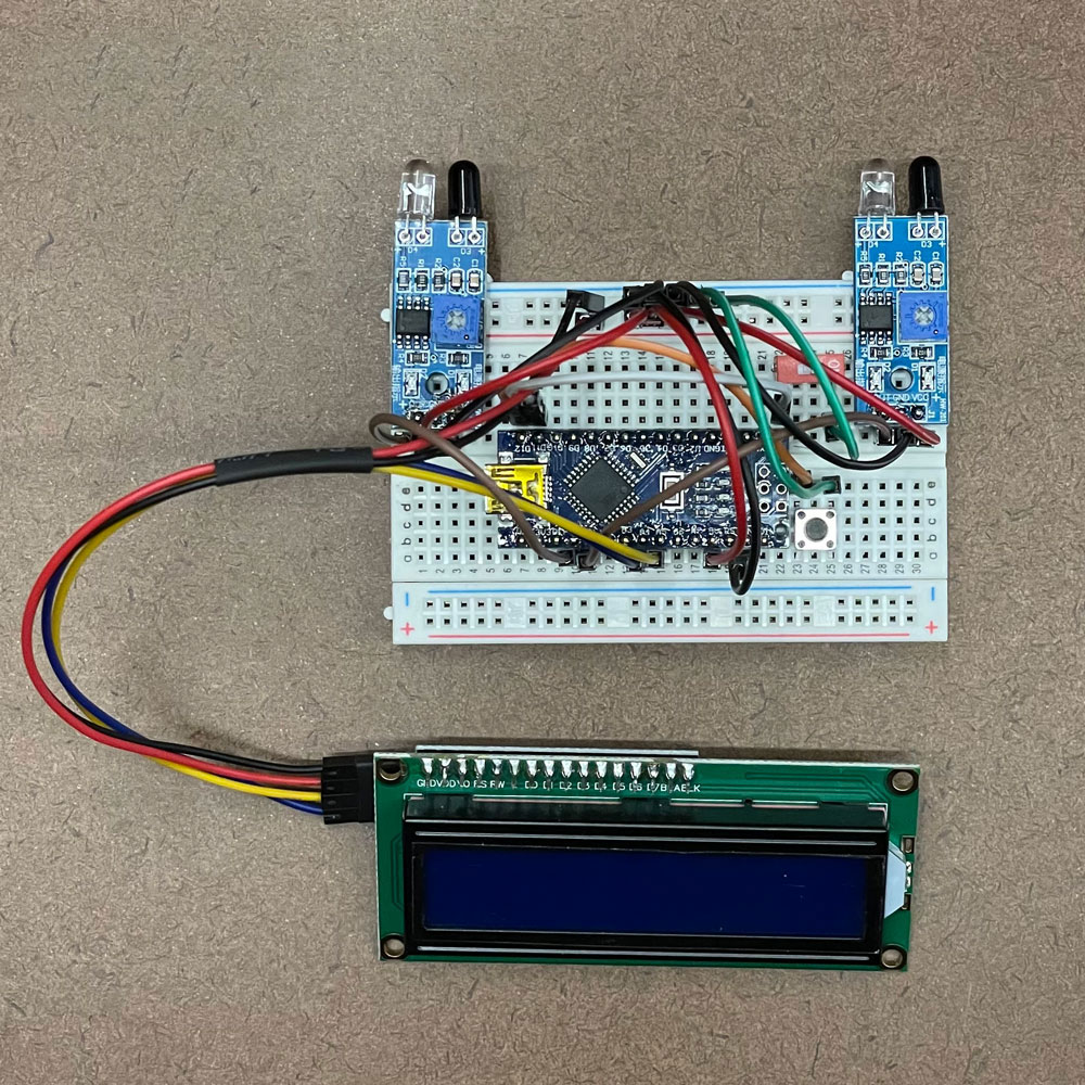
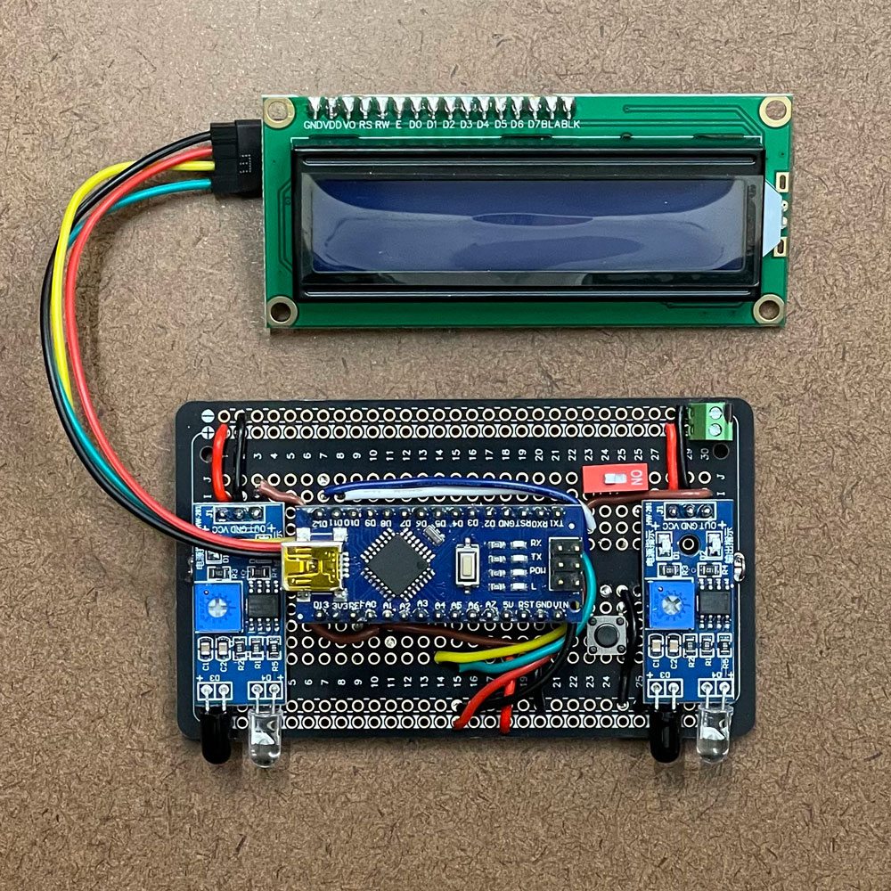
The electronics for the project were deliberately simple. An Arduino Nano handles the timing and calculations, two inexpensive infrared sensors detect the train, and a small LCD displays the result. I initially built everything on a breadboard while working through the software and sensor placement, then moved the project onto a more permanent prototype board once I was happy with it.
At the time, that was really all I was trying to accomplish. I needed a speedometer, so I built a speedometer, the way I wanted it.
- Scale: Z, N, HO, S, O, G
- Kits include v2 Components
- Bi-Directional
- DC or DCC
- Displays Scale Speeds
- Speed match your DCC locomotives
- 4 Different Sensor configurations
- Compact and portable
- On-board Status LEDs.
- It requires a 5v supply, USB, or direct for the Nano.
One Piece of a Larger Puzzle
What became more interesting over the years was the idea behind it.
The infrared sensors don’t actually know they’re part of a speedometer. One simply reports that something has happened at one location and another reports that something happened somewhere else. The Arduino gives those two events meaning. In this case it uses the time between them to calculate speed, but measuring speed is only one thing you can do once the railroad can tell you where something is happening.
A train passing a sensor might affect a signal. It might trigger lighting in a building, start an audio sequence, operate an animation or tell another part of the railroad that a train has entered or left an area. Two or more events can also be related to each other instead of every little electronic project underneath the railroad living completely on its own.
That’s part of the thinking behind IRROD, the system I’m currently developing for my own railroad.
IRROD isn’t simply this speedometer expanded into something larger, and I’m not trying to turn every old Arduino project I’ve built into part of it. But projects like this are where a lot of the ideas came from. They gave me a chance to experiment with sensors, microcontrollers and physical events on the railroad and start thinking about how those pieces could work together.
The speedometer still does exactly what I originally built it to do. Put a locomotive through the sensors and it tells me how fast it’s going.
It just turned out to be one small piece of a much larger puzzle.



About time you brought this one back. I remember the original speedometer project and always thought it was one of those simple Arduino projects that made you wonder why we don’t use these little boards for more things around the railroad. I’m looking forward to seeing what you do with version two and how it ties into IRROD.
I’m curious what everyone else is doing though. Are any of you using Arduino, ESP32 or similar boards around your layouts, or are you mostly sticking with dedicated model railroad electronics?
Thanks, Joseph. The speedometer was actually one of the projects that convinced me there was a lot more we could be doing with these little boards around the railroad. Version two is going to clean up some things I learned from the original and eventually give it a place within IRROD, while still keeping it useful as a standalone project.
I’m curious about that too. I know there are modelers experimenting with Arduino and ESP32 boards, but I don’t see nearly as much of it as I expected. Hopefully a few people will jump in and share what they’re building.
I am confused about acquiring an Arduino MRR Speedometer. When I select the order online button, I get this message “No Results Found. The page you requested could not be found. Try refining your search or use the navigation above to locate the post.” I researched Arduino and found various kits but nothing specific as a Model Railroad Speedometer. I am starting a new layout since moving and would like to incorporate one of these where it would be hidden.
I’m fairly new in model railroading so I might be missing something but would appreciate your help. On my last layout I used a tape measure and a timer. This looks significantly better.
Regards, Bill Motsinger
Hey Bill, thanks for reaching out. Right now, we are out of stock again. When these do go in stock, they don’t last very long. I am struggling to get one of the chips that I need to complete this build. I don’t have an ETA from China right now, I’m not that special 🙂 I have your information and will let you know as soon as I can build more inventory.
I would like to purchase one or more of the speedometer kits but I’d like to mount them permanently on the fascia. Is there a bezel that you’re aware of to fit the LED display?
Thanks in advance.
Craig, there are a couple of ways to mount these LCDs.
1. Amazon sells a 3D printed bezel (https://amzn.to/4i3PGml) that you can use double-sided tape to mount.
2. There are tons of 3D files you can download and print. (https://wcmrr.com/I2C-LCD-faceplate).
3. Is there a possibility that I could print one for you.