Building the T-Trak Modules, Part Two
At the end of Part One, both T-Trak modules had reached essentially the same point. The laser-cut plywood pieces had been assembled into finished wooden boxes, but they were still just boxes. The next step was turning them into working modules that could actually be connected to the rest of the Widow Creek Railroad.
The two modules serve very different purposes. The standard single module will eventually become Widow Maker Whiskey, while the depressed module will become the Old Sawmill and logging pond. They will sit together at the end of the switching puzzle, so even though their decks are different, I wanted the mechanical and electrical systems underneath them to work the same way.
That meant mounting the track, adding leveling feet, installing the electrical connections and building a backdrop system that could be removed for transportation. Just as with the wooden construction in Part One, most of those details were designed into the modules before the first piece of plywood ever went into the laser.
Mounting the Track Without Measuring It Every Time
Normally, installing Kato Unitrack on a T-Trak module involves positioning the two tracks against alignment tools, checking the required setback from the front of the module and making sure the two tracks remain parallel. There is nothing particularly difficult about doing that, but it is another opportunity for a small measurement error to work its way into the finished module.
I wanted the module itself to establish those positions.
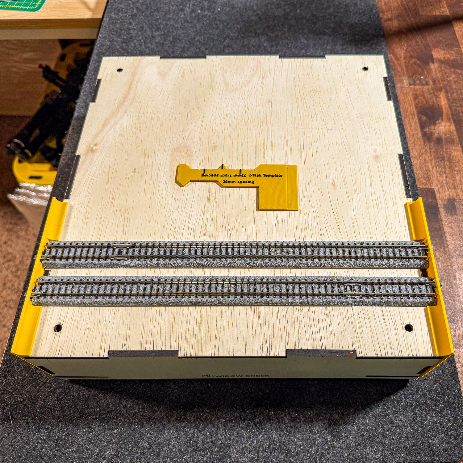
The laser-cut deck therefore includes the locations for the Kato mounting bosses, openings for the factory feeder wires and access holes for the leveling feet. The track can be placed directly onto the deck and its mounting points establish where it belongs without having to recreate the T-Trak track geometry with rulers and alignment gauges every time I build another module.
There was one complication. While working with several pieces of Kato track, I found that the physical locations were not absolutely identical from one piece to another. I even measured differences approaching a millimeter between nominally identical sections. A perfectly sized round mounting hole would therefore make the precision of the module work against me.
The mounting holes in the plywood are slightly oval instead. That small amount of movement lets the track settle naturally into alignment while still providing a positive mechanical mounting point.
Once positioned, the Unitrack is secured from underneath with M2 × 2 inch screws. On the standard single module, the hole pattern accommodates one 248 mm section and one 62 mm section in either orientation. The Kato feeder leads simply pass through their corresponding openings in the deck and disappear underneath the module.
The result is repeatable alignment without requiring the alignment tools that were necessary when I originally laid out T-Trak track by hand.

Leveling and Wiring the Module
A T-Trak module has to do more than sit flat on my workbench. It has to line up with modules built by other people on tables and floors that may be anything but flat.
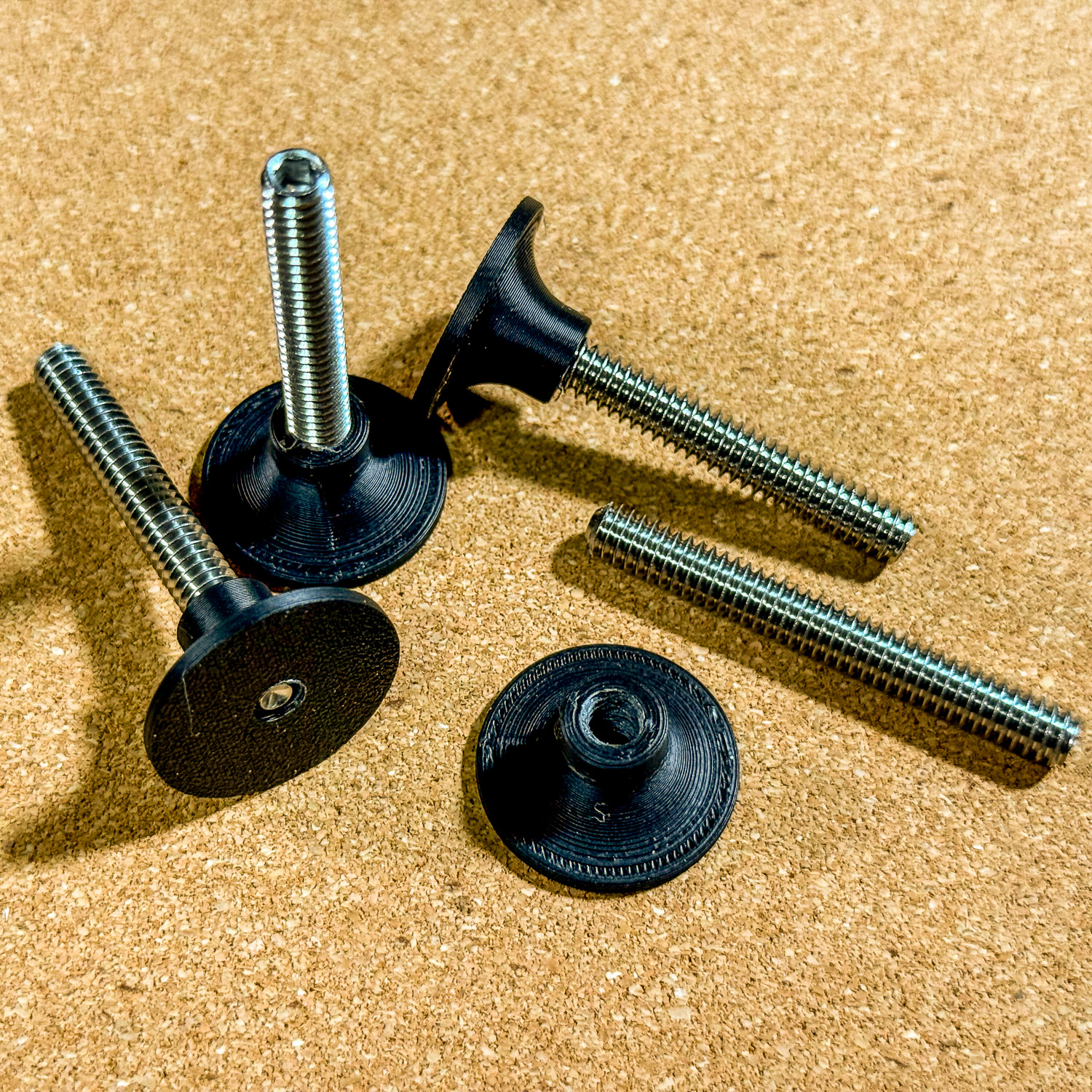
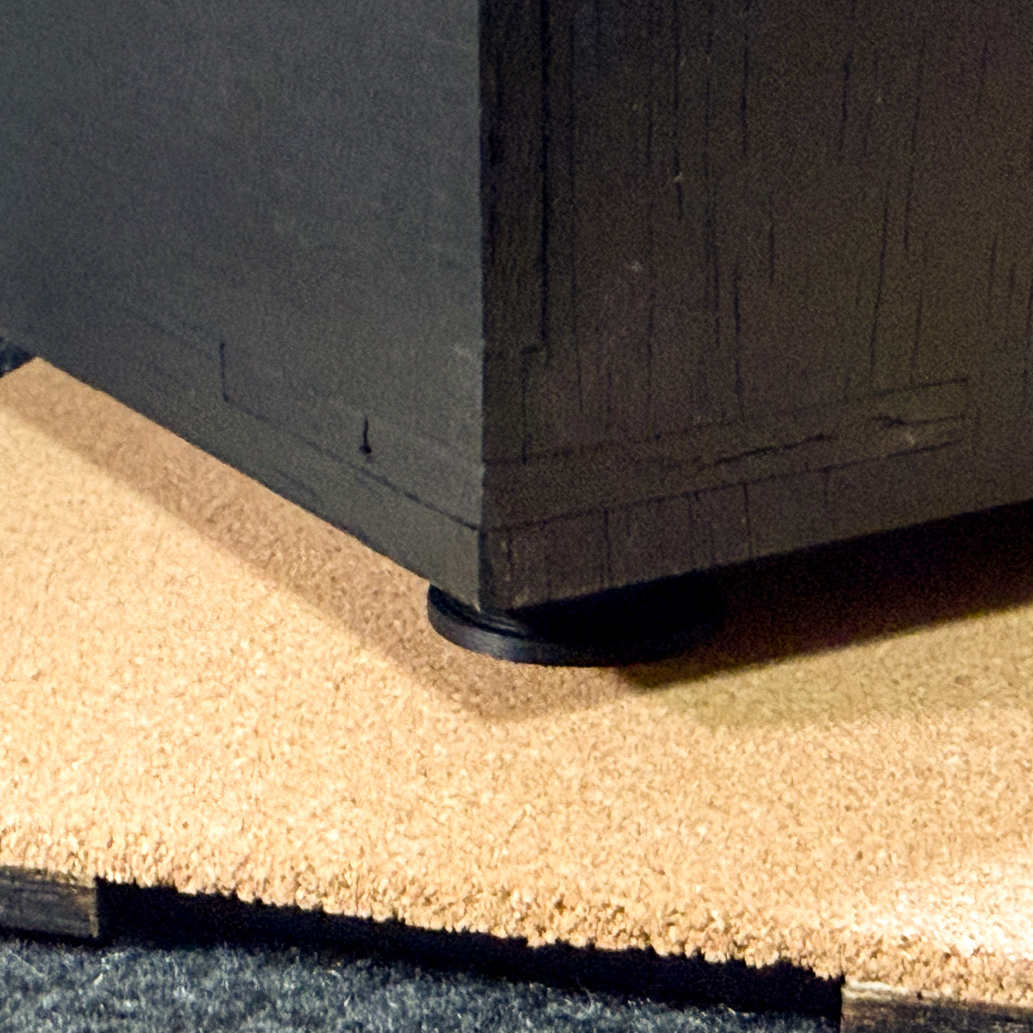
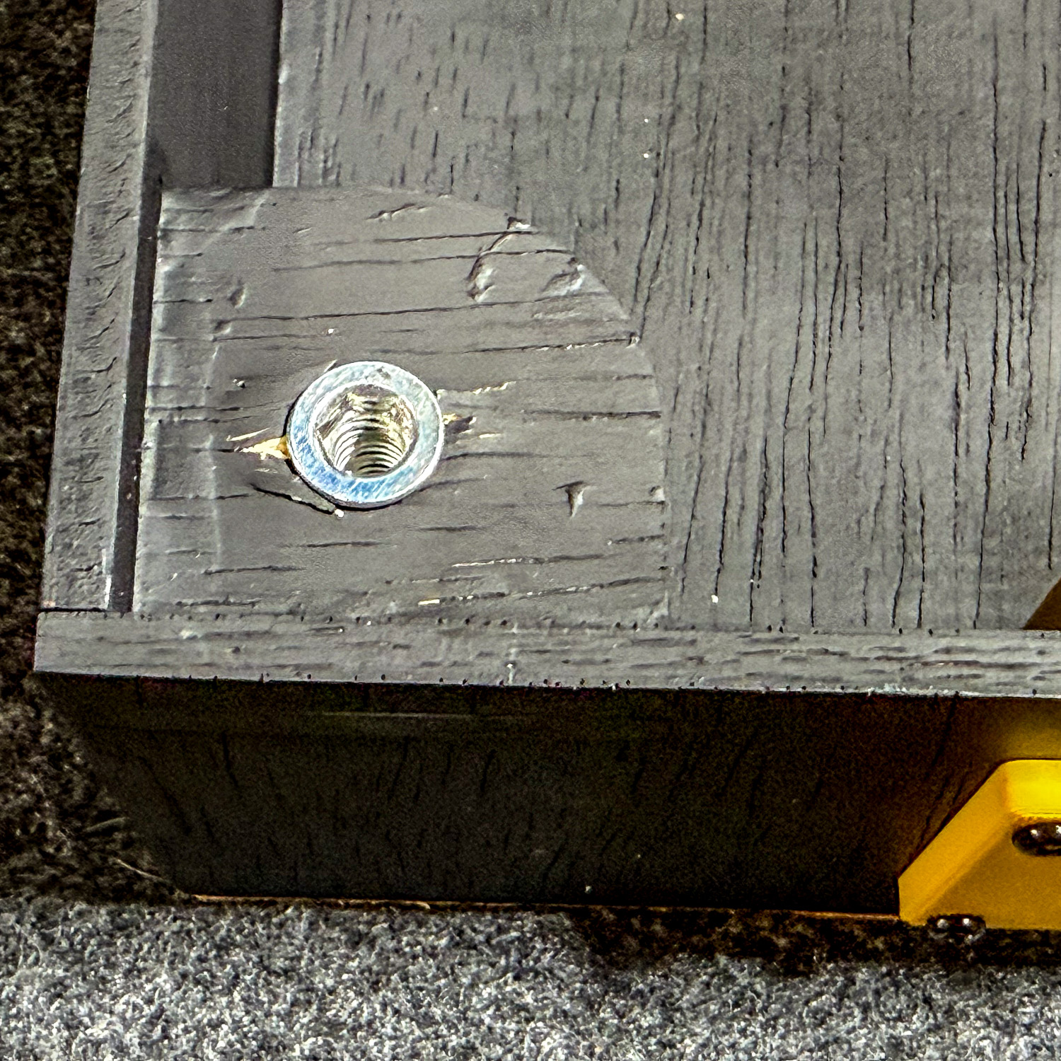
Each corner therefore has a 1/4-20 threaded insert for an adjustable leveling foot. The small holes visible from the top of the deck provide Allen key access, so the height can be adjusted without having to reach underneath the module or remove anything from the top.
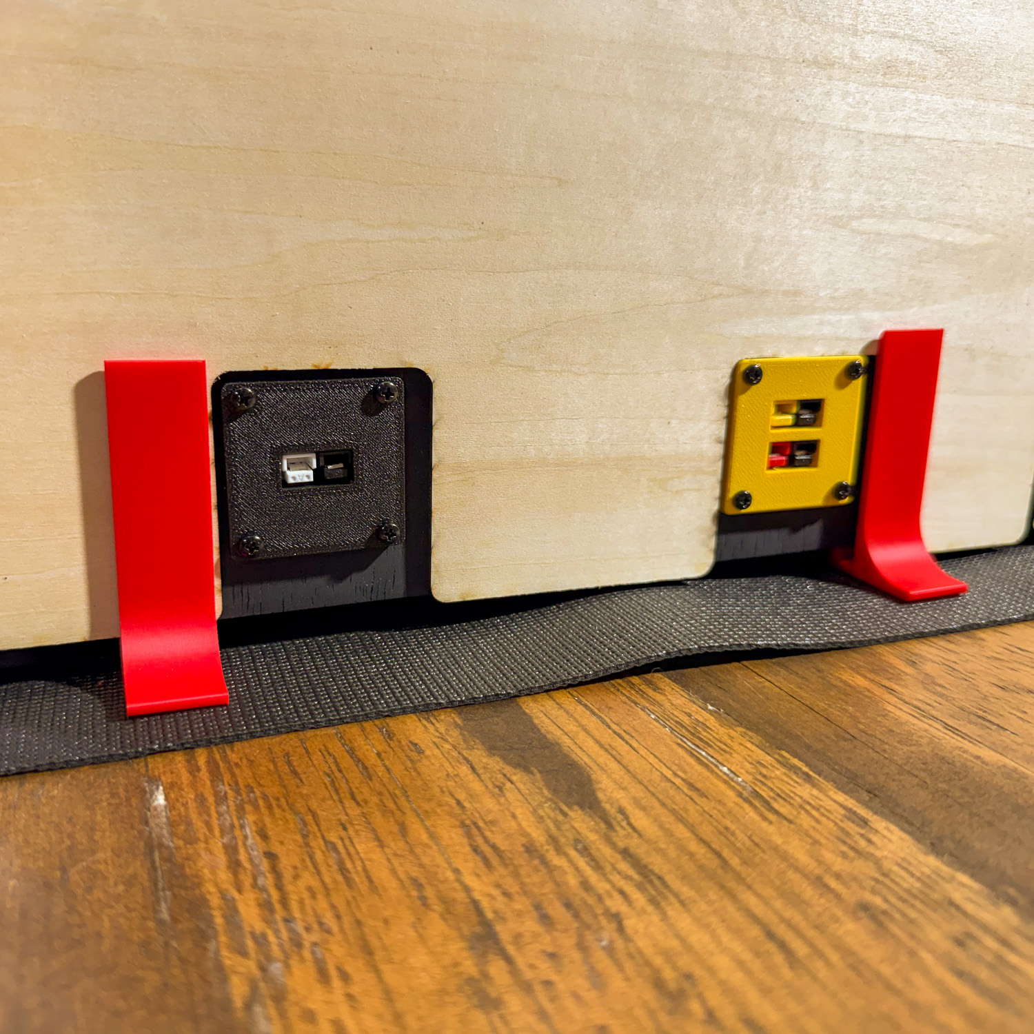
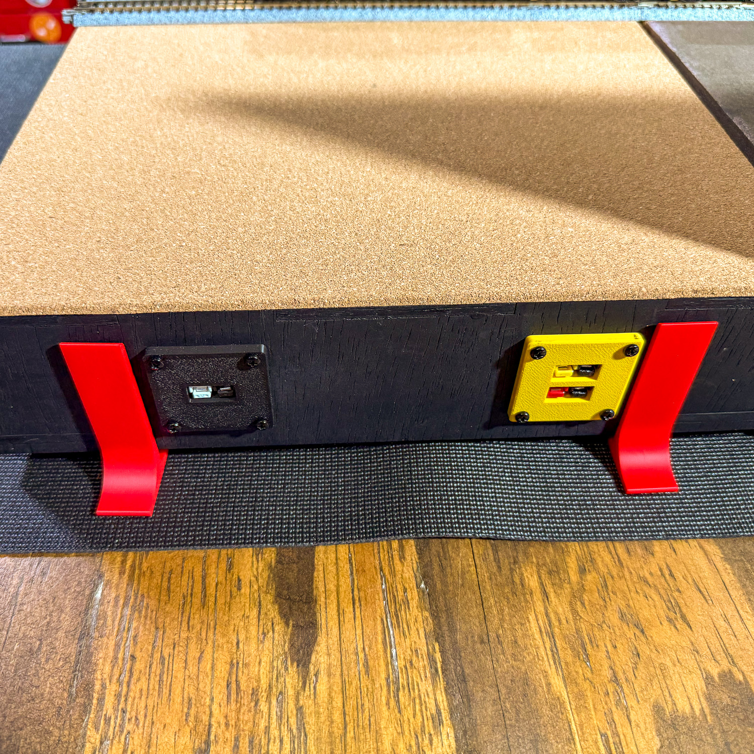
Electrical connections are handled in much the same way. Rather than having loose connectors hanging beneath the module, the rear panel was designed from the beginning to accept the connection hardware.
The track feeders come underneath the deck and terminate at the electrical distribution point. Anderson Powerpole connections provide the external track bus connection between modules, while a separate 12-volt DC circuit is available for lighting, sound boards and other accessories that will eventually be installed on the module.
Keeping those two systems separate was intentional. Track power remains track power, while scenery electronics have their own supply and do not need to borrow power from the rails.
The finished wiring is deliberately simple and accessible. If something fails during a show, I want to be able to turn the module over, see where every wire goes and service it without dismantling the module.

A Backdrop That Belongs to the Module, But Not Permanently
The backdrops presented a different problem.
I wanted each module to have a backdrop specifically designed for the scene, but I did not want a large sheet of plywood permanently attached to the module. A fixed backdrop makes the module harder to transport and creates a large lever that can transfer an accidental bump directly into the module.
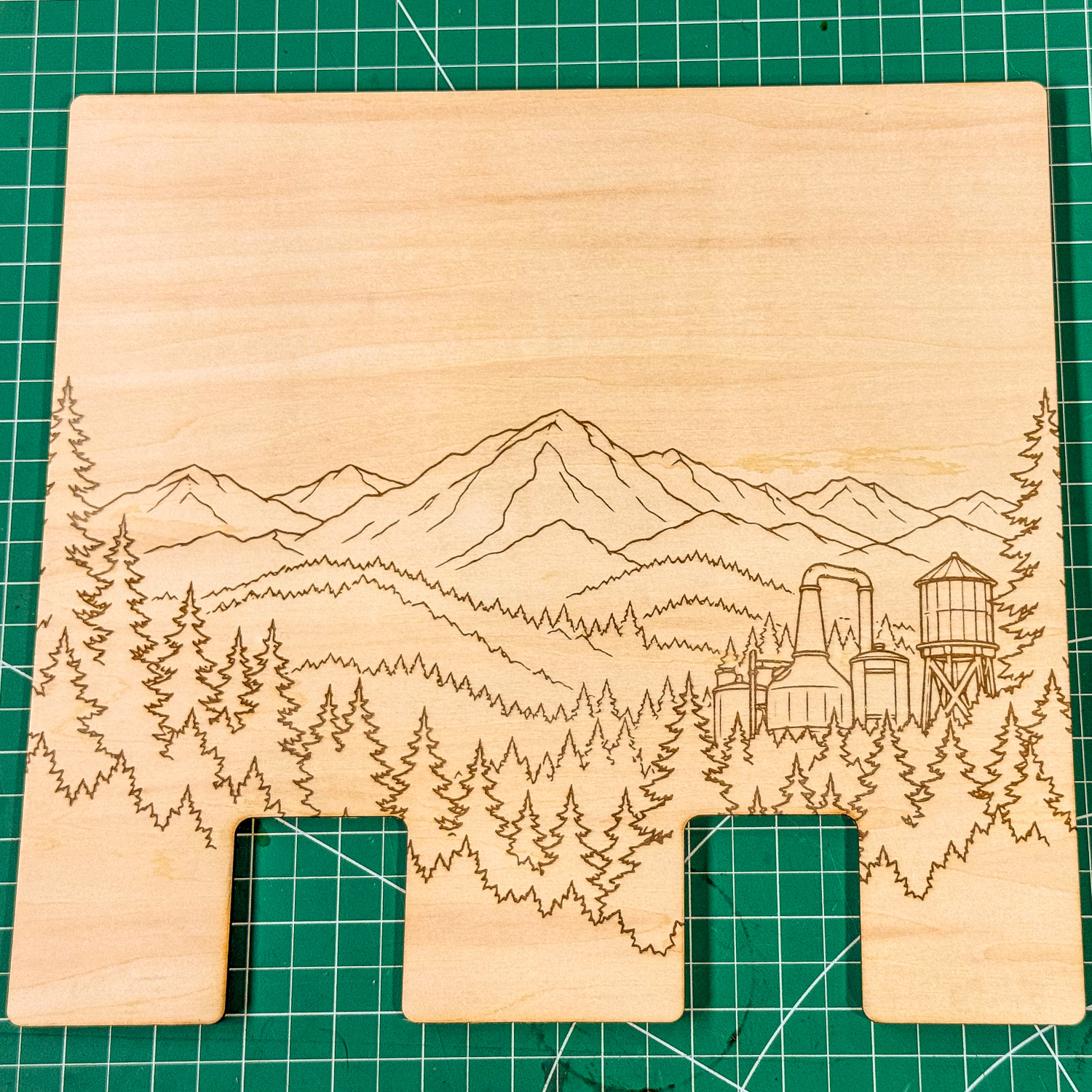
Instead, the backdrop is a separate laser-cut panel held by 3D-printed mounts at the rear of the module. The mounts establish its position and keep it stable during use while allowing the entire backdrop to be removed when the modules are packed.
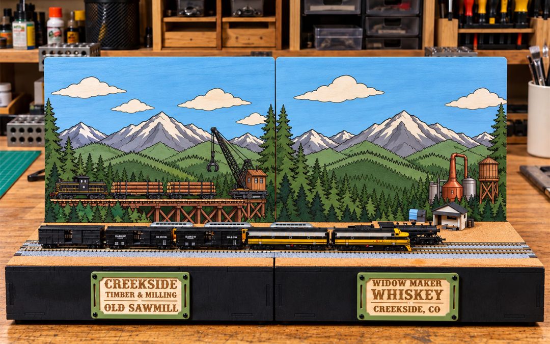
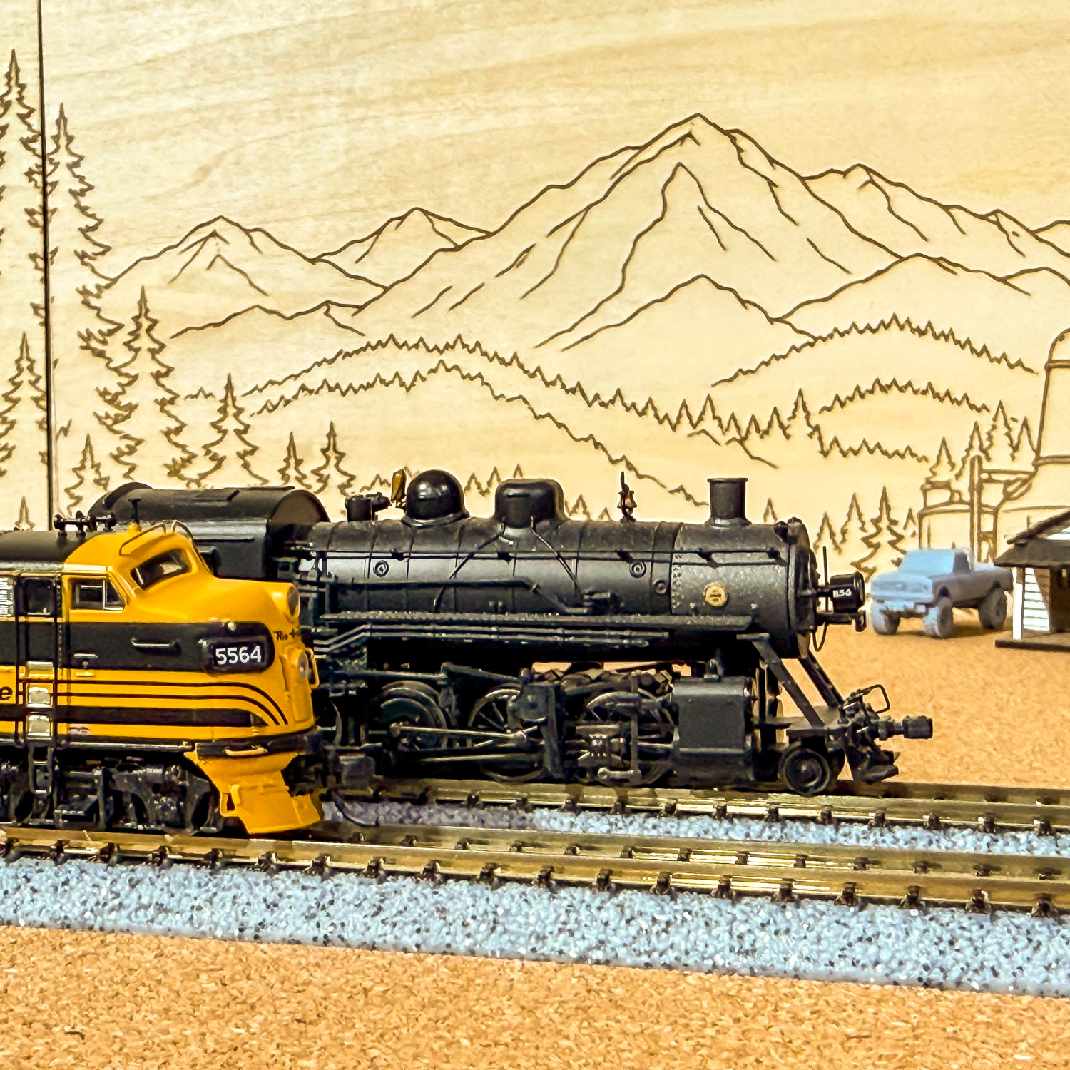
The artwork for both scenes was converted into line art and laser engraved directly into the wood. The Old Sawmill backdrop carries the mountain, forest, logging bridge, locomotive, log cars and crane scene. Widow Maker Whiskey uses the same mountain environment but transitions into the distillery and water tower.
Placed next to each other, the two panels are separate pieces, just like the modules themselves, but the landscape is designed to read as one continuous environment.

sing the Laser Engraving as a Paint by Number Guide
he engraving has another purpose beyond adding detail to the plywood.
Before cutting the final backdrops, I experimented with turning the artwork into a simplified paint by number system. The idea is to use the laser-engraved lines as the boundaries for the major colors rather than trying to reproduce a photographic backdrop.
The palette breaks the scene into a relatively small number of colors: sky blue, cloud and mountain snow whites, mountain gray, several layers of greens for distant hills and foreground evergreens, plus the appropriate wood, metal and industrial colors for the sawmill and distillery elements.
The paint by number mockups show what those engraved panels should eventually look like once those colors are applied.


That gives me something between a traditional painted backdrop and an engraved illustration, while also making the painting process much more approachable. The laser has already done the drawing. Painting becomes a matter of working within the engraved areas and building the scene one color at a time.
At this stage, however, that is as far as the scenery goes. These two modules are still construction projects. The foam on the depressed module simply demonstrates why its deck was lowered, and the painted backdrop examples show where the laser-engraved panels are headed. Building the logging pond, sawmill, distillery and surrounding scenery comes later.
For now, the important part is that the underlying modules are complete. The track has a repeatable mounting system, the modules can be leveled, the electrical connections are contained and accessible, and the backdrops can be installed or removed without becoming a permanent structural part of either module.
What started in Part One as a drawing on a computer and a sheet of plywood has now become two functional T-Trak modules ready for the next stage of the Widow Creek Railroad.
Photo Gallery